(770) 529-4731
esen

7 Tips for Choosing the Right Diode Sensor?

Choosing the right Diode Sensor can influence measurement accuracy, response speed, operating life, and total system cost. A sensor may look suitable on paper, yet fail beside a hot motor, bright lamp, or dusty production line. That difference matters.

Jacob Fraden, a recognized sensor technology author, defines a sensor as “a device that receives a stimulus and responds with an electrical signal.” This principle guides every practical Diode Sensor decision. The device must respond to the intended light, temperature, or radiation level. It must also remain stable when conditions become less friendly.

This guide presents seven practical tips for selecting the right Diode Sensor. It examines spectral range, sensitivity, response time, noise, temperature behavior, package design, and circuit compatibility. These factors are connected. Improving sensitivity may increase noise. A faster sensor may require more demanding electronics. A compact package may struggle with heat removal.

Start with the measurement target. Is the sensor detecting a weak infrared signal, monitoring laser output, or measuring changing illumination? Each task needs different specifications. Check real operating conditions, not only laboratory values. Include cable length, optical filters, ambient temperature, vibration, and calibration requirements.

A datasheet is useful. It is not the whole answer.

Engineers should compare test results from actual installations whenever possible. They should question impressive specifications that lack measurement conditions. I have found that selection mistakes often come from overlooked details, such as connector leakage or window contamination. These issues are easy to underestimate.

The best Diode Sensor is not always the most sensitive model. It is the model that delivers dependable signals within the complete system. That choice requires technical judgment, careful testing, and willingness to reconsider early assumptions.
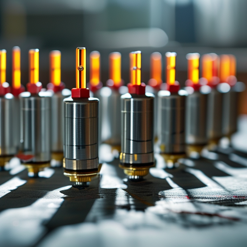
7 Tips for Choosing the Right Diode Sensor?

Define Your Measurement Needs and Operating Conditions

Choosing a diode sensor starts with the measurand, not the component catalog. Define whether you need irradiance, pulse energy, position, or simple light detection. Record the target wavelength, minimum signal, maximum signal, response time, and acceptable error. A 2023 NIST technical report identifies spectral responsivity, linearity, and temperature as major photodiode measurement concerns. That matters in practice.

Check the operating scene. A sensor near a furnace may face high temperature, vibration, and stray infrared radiation. A laboratory detector may instead need low noise and stable readings below microampere levels. Match the active area to the beam size. A large area captures more light, but it usually adds capacitance and reduces bandwidth. For pulsed signals, review junction capacitance, reverse-bias limits, and amplifier noise together. Do not choose sensitivity alone.

Industry data also supports careful qualification. The Semiconductor Industry Association reported global semiconductor sales of 526.8 billion dollars in 2023, showing how broad the supply chain has become. Availability does not guarantee measurement fitness. Test the sensor with your real source, cable length, enclosure, and temperature range. I once underestimated reflected light from a matte metal surface. The readings looked stable, but they were wrong. That mistake still deserves attention. Use calibration records, uncertainty budgets, and repeatability tests before approval.


Compare Diode Sensor Types and Detection Principles

7 Tips for Choosing the Right Diode Sensor

Choosing a diode sensor begins with its detection principle. A photodiode converts incoming light into a measurable current. A PIN photodiode uses an intrinsic layer for fast response and low capacitance. It suits pulse detection, optical measurement, and moderate light levels. An avalanche photodiode adds internal electrical gain. However, it needs higher bias voltage and careful noise control. Compare sensitivity, wavelength range, and response speed before selecting a type.

Match the sensor to the light source. Check whether it detects ultraviolet, visible, or infrared wavelengths. A Schottky photodiode can provide quick response in some short-wavelength applications. Review the active area carefully. A larger area collects more light, but it may respond more slowly. Consider the seventh factor: operating temperature. Dark current can rise noticeably in a warm enclosure. It can quietly reduce measurement stability.

Practical testing matters more than a data sheet alone. Place the diode at the expected distance, then measure output under real background light. Check whether the signal remains clear after amplification. Shielding may help, but it cannot fix a poor spectral match. I once treated sensitivity as the main priority and overlooked saturation from a bright source. That was a useful mistake. The best choice also considers bias requirements, circuit compatibility, long-term drift, and calibration access. Perform a simple trial before final installation.

7 Tips for Choosing the Right Diode Sensor

Compare diode sensor types by spectral response and detection principles before selecting a detector for your application.

How to Read the Chart

The chart shows typical usable wavelength ranges for common photodiode materials. Silicon is suitable for visible and near-infrared light, while germanium and InGaAs are better suited to longer near-infrared wavelengths. UV-enhanced silicon extends detection further into the ultraviolet range.

  • Match the sensor material to the wavelength of the target light.
  • Check whether the application requires ultraviolet, visible, or infrared detection.
  • Choose a PIN photodiode for fast, linear light measurement.
  • Consider an avalanche photodiode when higher internal gain is required.
  • Review responsivity and detectivity, not only the wavelength range.
  • Check dark current and temperature stability for low-light measurements.
  • Verify the sensor's active area, response speed, and electrical interface.

Evaluate Wavelength Range, Sensitivity, and Response Speed

Choosing a diode sensor starts with the measured light, not the lowest price. Silicon devices typically cover about 400–1,100 nm, while indium gallium arsenide devices often reach 900–1,700 nm. These ranges reflect common industry data sheets and photonics measurement reports. Check the source spectrum carefully. A red LED and a near-infrared laser may look similar, but they need different sensor materials.

Tip 1: Match the wavelength range. Sensitivity must also be tested at your operating wavelength. A sensor may show 0.6 A/W at one wavelength, but much less elsewhere. Review responsivity curves, dark current, and noise-equivalent power. NIST calibration guidance emphasizes traceable measurements, yet field conditions can still change results. Dust, temperature, and optical reflections matter.

Tip 2: Measure response speed in the real circuit. A 10 ns sensor can perform poorly with long cables or excess capacitance. Industry reports on optical receivers commonly compare bandwidth in MHz or GHz, but bandwidth alone is not enough. Check rise time, load resistance, and amplifier limits.

Tip 3: Test before approval. Use the actual light source, pulse pattern, and temperature range. My practical mistake was trusting a headline sensitivity value. It looked impressive. The complete curve told a different story.

Check Compatibility, Reliability, and Environmental Protection

Choosing the right diode sensor starts with compatibility, not price. Confirm its spectral response matches the light source and measurement range. Check the output type, bias requirements, connector, and signal-conditioning circuit. A sensor can fit mechanically yet fail electrically. Test it early.

Reliability depends on more than a clean datasheet. Review measurement drift, noise, response time, and expected operating hours. Ask for calibration records and traceability from a competent laboratory, preferably one following ISO/IEC 17025 practices. In field projects, I have seen small connector weaknesses create unstable readings after repeated cable movement. The original design was technically correct, but the installation was not.

Environmental protection deserves equal attention. Examine the operating temperature, humidity limits, vibration resistance, and resistance to dust or moisture. An enclosure rated under IEC 60529 may help, but the rating applies to the complete installed assembly, not always the bare sensor. Use sealed cable entries and avoid placing the diode near condensation points. Small leaks matter. If chemicals, outdoor sunlight, or rapid temperature changes are present, request test data for those conditions. I sometimes prefer a slightly less sensitive sensor with stronger protection. It may produce fewer impressive laboratory results, but more dependable field data. Review the choice after a trial period; early assumptions are often wrong.

Balance Installation Requirements, Cost, and Long-Term Support

7 Tips for Choosing the Right Diode Sensor?

Balance Installation Requirements, Cost, and Long-Term Support

Start with the installation site, not the product list. Measure available space, cable routes, temperature, vibration, and light exposure. Confirm the sensing range and response speed match the application. Check connector access before ordering. A sensor that fits electrically may still be difficult to mount. Ask whether calibration can be completed after installation. Test one unit in the real environment.

Review the total cost, not only the purchase price. Include mounting parts, wiring, calibration, replacement labor, and possible downtime. Compare accuracy with the value of the measurement. A cheaper sensor can become expensive when readings drift. Request clear tolerance data and maintenance intervals. Also check power requirements. Small differences can affect a large installation. Keep a reasonable spare-parts plan.

Long-term support deserves equal attention. Confirm technical documentation, troubleshooting guidance, and expected service life. Ask how quickly replacement units can be supplied. Verify whether firmware, calibration, or repair services remain available. Speak with engineers, not only sales staff. Their answers often reveal practical limits. Avoid choosing a sensor based on one impressive specification. Field performance can differ. I once underestimated cable routing, and the installation needed extra labor. That mistake was avoidable. Leave room for future changes, too. Standards may evolve, and your equipment may expand. A short trial, recorded test results, and honest review notes can prevent a costly decision.

7 Tips for Choosing the Right Diode Sensor? - Balance Installation Requirements, Cost, and Long-Term Support

Tip Selection Dimension Practical Specification or Target Installation Requirement Cost and Performance Effect How to Verify Before Purchase Priority
1 Match the sensing wavelength Choose a photodiode whose specified spectral-response range covers the source wavelength. Silicon devices commonly cover approximately 400–1,100 nm, while InGaAs devices are commonly used for approximately 900–1,700 nm. Confirm that optical filters, windows, and covers do not block the required wavelength. Avoid relying only on visible-light sensitivity when the system operates in infrared. A correct spectral match improves signal level and may reduce the need for high-gain amplification. A mismatched sensor can create low sensitivity, noise, and additional optical costs. Compare the sensor’s responsivity curve with the source wavelength and request measured responsivity at the actual operating wavelength. High
2 Size the active area and field of view Select an active area large enough to capture the expected beam or light spot, but not unnecessarily large. Smaller active areas generally support lower capacitance and faster response. Allow for alignment tolerance, beam movement, mounting clearance, and any diffuser or lens used in front of the sensor. Larger-area devices can simplify installation and alignment, while smaller-area devices can improve bandwidth. An optical concentrator may reduce sensor size but adds alignment sensitivity and component cost. Calculate the maximum spot diameter and position error. Confirm the active-area drawing, acceptance angle, and mechanical tolerances. High
3 Set the required speed and bandwidth Choose a sensor and amplifier with a bandwidth comfortably above the highest signal frequency. For pulsed or rapidly modulated light, check rise time, junction capacitance, and reverse-bias conditions. Keep leads short, use suitable shielding, and control cable capacitance. The enclosure and amplifier layout should minimize electromagnetic interference. High-speed sensors and amplifiers usually cost more and may require tighter PCB design. Selecting excessive bandwidth can increase noise without improving measurement results. Request rise time, junction capacitance, noise-current data, and frequency-response plots under the intended bias and load conditions. High
4 Check signal level, linearity, and dynamic range Estimate photocurrent using the approximate relationship: photocurrent = responsivity × optical power. Verify that the maximum signal remains below the sensor and transimpedance amplifier limits. Provide a stable optical path and prevent saturation from direct or reflected light. Add an aperture, attenuator, or optical filter where necessary. A sensor with adequate dynamic range reduces clipping and recalibration. Excessively sensitive components may require attenuation, while low-sensitivity components may require a more expensive low-noise amplifier. Test minimum, nominal, and maximum optical power. Review linearity error, saturation level, dark current, and output noise over the operating temperature range. High
5 Confirm environmental and packaging requirements Check operating temperature, humidity, vibration, ingress protection, window material, and connector requirements. The selected package should meet the actual installation environment rather than only laboratory conditions. Use appropriate sealing, strain relief, grounding, and thermal design. Avoid condensation and keep the optical window clean and protected from abrasion. Rugged packaging may increase purchase price but can reduce field failures, contamination, and maintenance labor. Environmental mismatch can shorten service life and invalidate calibration. Review the environmental rating, temperature coefficient, storage limits, vibration data, material compatibility, and installation instructions. High
6 Compare total installed cost Evaluate the complete cost of the sensor, mounting hardware, optics, amplifier, cables, connectors, shielding, calibration, installation time, and replacement inventory. Prefer a package that fits existing brackets, cable routes, power supplies, and signal interfaces when performance remains acceptable. The lowest unit price may lead to higher alignment, wiring, calibration, or integration costs. A moderately priced sensor with compatible interfaces can reduce total project cost. Build a three- to five-year cost estimate covering purchase, installation, calibration, expected replacements, downtime, and technician time. Medium
7 Assess calibration and long-term support Choose a supplier that can provide traceable calibration information, stable revision control, technical documentation, replacement availability, and a defined support process. Plan access for inspection and replacement. Record serial numbers, calibration dates, installation orientation, and the recommended recalibration interval. Documentation and continuity support may add little to the initial cost but can significantly reduce troubleshooting time, production interruptions, and measurement drift over the service life. Request a sample calibration certificate, product-change notification policy, expected availability period, repair or replacement procedure, and technical response targets. High

Note: Actual performance depends on the sensor material, optical configuration, amplifier design, temperature, and installation conditions. Verify all limits using the final application test setup.